| Many
Bricksters have experienced no-start problems that were
later traced to the fuel pump relay unit. On closer
inspection, it was often discovered that the source of
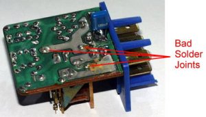
the problem was bad solder joints inside the unit where
the the actual electromagnetic relay is soldered to the
circuit board. The bad joints would work for many years,
but would eventually get very hot because of their
increased resistance. This heat would often show up as
burn marks on the circuit board or on the relay, and in
extreme cases would discolor or melt the plastic casing
of the unit. In many cases
the bad solder joints can simply be resoldered. Even if
you do decide to replace the unit rather than repairing
it, resoldering the joints of the old one will often
yield a perfectly usable spare.
 Description Description
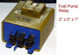
The fuel pump relay unit on
1978-on (or so) K-jetronic-equipped 240s is actually more
than just a simple relay. It also contains a circuit that
listens to the ignition system to determine whether the
engine is running. When the unit detects an ignition
signal, it switches the fuel pump on. When the ignition
signal stops, it switches the pump off.
Locating the Fuel Pump Relay
Unit
The fuel pump relay unit is
located under the dashboard in the vicinity of the
steering column. I have found them clipped to the
crossmember where the steering column mounts; and I have
also found them mounted higher up between the instrument
cluster and the firewall. The unit is usually either
black or mustard yellow and has a six-blade connector on
one end.
Opening the Unit
After locating and removing the
relay unit, pop open the plastic casing by prying the
case apart so that the end with the connector slides past
the retaining wedges. This is a little bit difficult, but
can be done without damaging the unit.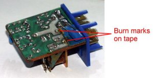
Inspecting the unit
Once you've got the unit open,
the first thing to do is check for a faint burnt odor.
This would indicate whether or not it's gotten too hot in
there.
Next, check for burn marks that
would indicate excessive resistance. You'll usually find
them on the circuit board near the offending connections
or components.
Next, put your thumb on the big
relay on the circuit board and try to wiggle it. If the
big part of the relay (not the small hinged part) wiggles
at all, its solder joints are bad and must be
re-soldered.
 Check
the contact points between the hinged and stationary part
of the relay. It's hard to say how much pitting or
discoloration is normal, but all of them that I've looked
at (including the perfectly good ones) have had a little
pitting. If they're really bad, you may be able to extend
their life by sanding them, but's impossible to say how
much Check
the contact points between the hinged and stationary part
of the relay. It's hard to say how much pitting or
discoloration is normal, but all of them that I've looked
at (including the perfectly good ones) have had a little
pitting. If they're really bad, you may be able to extend
their life by sanding them, but's impossible to say how
much
On the solder-side of the cicuit
board, check that all of the solder joints are smooth and
shiny. A Dull or crinkly appearance indicates poor
soldering.
|