| PRV-6 Idle Setting Procedure | Design for an LED Sensor to Diagnose the V-6 | |
One thing that could be causing your surging
idle is a dirty throttle body. This is a real problem, if the TB is plugged
so badly that all air regulation at idle goes through the Aux Air. Clean
the throttle body, it's easy enough, but DON'T adjust the throttle stop.
Just to make it clear DON'T ADJUST THE THROTTLE STOP - not till later.
Just clean the TB.
Now, you're going to want to balance the
airflow to the cylinder banks:
The B28E has three adjustment screws near the throttle housing, the rear one is for the idle speed and about the other two the manuals only ever say: "don't touch". It did need balancing afterwards, so here's what I did:
1. Run engine for 15 minutes so that it
warms up.
2. Turn rearmost (idle speed) screw in
fully. That closes a passage to the front two (balancing) screws so that
turning them at this point won't have any effect.
3. Adjust the throttle stop so that the
engine runs at 700 rpm. May be a little rough, but never mind.
4. Turn two front screws in fully.
5. Turn rear screw out four complete turns.
Since step 4 resulted in the idle air passages to both banks being closed,
this should not change the idle speed at all.
6. Connect rev counter (handheld meter,
not the dashboard kind) and note the exact idle speed at this point. Should
still be 700rpm.
7. Turn out center screw three complete
turns. Note the new idle speed, should be around 1100-1200 revs, but this
isn't critical. Just make a note of whatever the number is.
8. Turn center screw back in fully, turn
out front screw so that the engine speed increases to the same as measured
in step 7. If you can't make it go that far, turn front screw out three
complete turns, measure the new idle speed, turn front screw back in completely,
then turn out centre screw to match the speed measured previously. The
object of this exercise is to find the number of turns for both screws
which will result in the same increase in idle speed. For one, that'll
be EXACTLY three turns, for the other whatever it takes. Set each screw
to the
number of turns you so determine. Idle
speed should be at about 1300-1400 rpm afterwards.
9. Finally, use the rear screw to get
idle down to 900 rpm. Then check CO level and adjust if necessary. If you're
a perfectionist, take the car for a few minutes' drive, then check idle
speed and CO again.
To return to the story, When rigged the LED flashes 6 times (indicating that the sensor which sits on the #1 spark plug lead is not working). Is there any EASY way I can confirm the non operation of this sensor?
Another request. Periodically, the
car does not start easily (engine turns for about 20 to 30 seconds)when
the engine is hot and the car has been standing for say 30 mins. When it
does start there is a faint smell of fuel. I have been advised
via brickboard that it could be the flywheel sensor. Here in Aus I have
been quoted equiv usd $120 for the part so naturally I am keen to confirm
that the flywheel sensor is not working before purchasing a new one. I
would appreciate it if someone had a way of confirming the operation of
this sensor as well.
[Response: Abe Crombie] The #1 plug wire
sensor is polarity sensitive. Make sure the wires on coil are correct,
red/white on terminal labeled 1 and blue on the terminal labelled 15.
The sensor could be on plug wire reversed if someone changed the wire and
slid it on wrong. This wouldn't make it have start problems when
hot. The sensor is used to ID the firing order for proper knock sensor
use since it has two knock sensors.
Pull the vac hose off of the fuel pressure
regulator and see if it has any fuel residue in it. Run the engine and
then immediately remove the return line off the fuel pressure regulator
(soft rubber hose held by clamp) and see if any fuel continues to drip
out of regulator. Any loss of residual pressure from system will cause
hot, short shutdown starting problems. A dripping leaking fuel injector
would do the same. The best way to check this out would be to use
a fuel pressure gauge if available. The check valve on fuel pump can also
allow fuel pressure loss when shut down.
[Design by Alex Dermedgoglou]
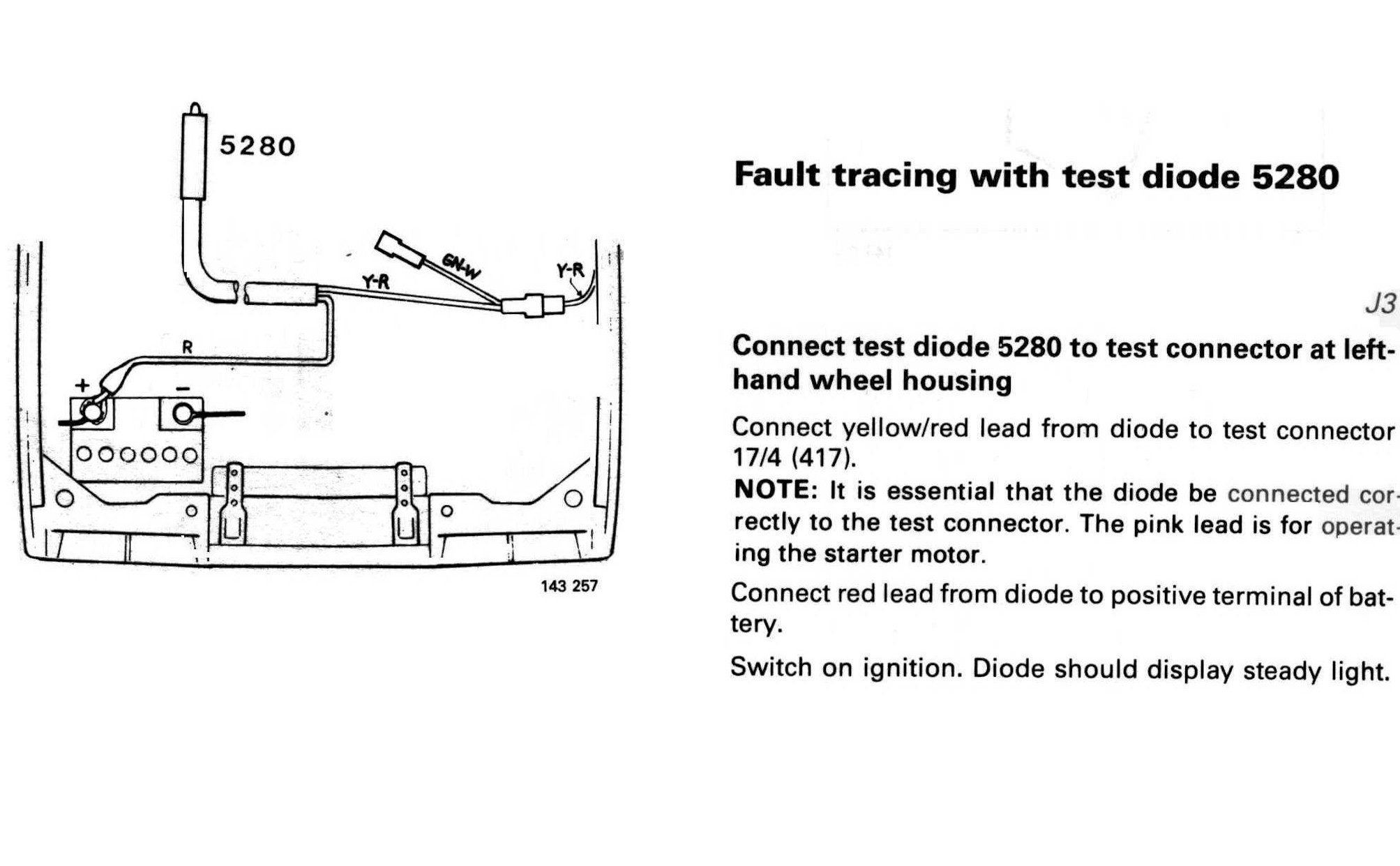
To make the number 1 cylinder sensor and flywheel sensor you need the following parts:
Assembly:
To use (see the attached diagram):
